NB-IoT Signal Tester Using ACR-EX Converter
Quick guide on use of ACR-EX-1xxNILCD-I1-C converter for NB-IoT signal testing.

Introduction
This manual provides a quick guide on effective use of ACR-EX Display Enabled Pulse to NB-IoT Converter as a Signal Tester. Signal Tester mode of ACR-EX is an effective solution for signal testing of an NB-IoT network.
Typical Use-Case
The typical use-case for the Signal Tester is to measure and analyze the signal strength of an NB-IoT network.
Functions
- NB-IoT signal level with display indication
- Configurable connection parameters
- Configurable sampling period intervals
Typical Signal Use-Case Testing Scenarios
- NB-IoT network testing before smart meter deployment
- Testing for viability of NB-IoT implementation
- Optimization of an NB-IoT network
- Maximum Transmission Unit (MTU) testing and validation
- Round Trip Time (RTT) testing with display Indication
- Two-way communication testing
Signal Tester Integration
Out of the Box Behaviors
By default, the converter is set to Pulse Counter mode. To set the device to Signal Tester mode, you need to follow the steps in the IEC Device Management section.
Requirements
In order to set up the ACR-EX as Signal Tester, you are going to need the following: an optical probe and our GUI. A SIM card is also required for functioning of NB-IoT.
❗Note, that you may not need to set up the device yourself, if you order the pre-configured package. For more details contact our Sales Manager at smetana@acrios.com or Support at support@acrios.com.
Optical Probe
For the IEC mode of communication, you will require an optical probe, often referred to as an optical port or optical head. It's a device used for communication with energy meters that support the DLMS/COSEM protocol according to the IEC 62056-21 standard. If you lack such equipment, we recommended and offer the following optical head.
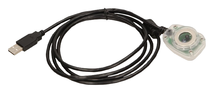
We offer ORNO optical probes for the management of our devices (datasheet: EN).
If you wish to order the probes from ACRIOS, use the order code of: Opticka_hlavice_USB-E379
GUI
To manage the device with ACR-EX GUI you need a Chromium-based browser (Google Chrome is strongly recommended to ensure a smooth operation).
Please note, in order to use the optical head, it is necessary to have installed the appropriate drivers.
Installation Guide for Windows
- Head to the following link and download the CP210x Universal Windows Driver.
- Extract the zip file.
- Using Windows File Explorer, locate the driver folder (that you previously unzipped).
- Right click on the silabser.inf file and select Install.
- Follow the prompted instructions.
SIM Card
Due to nature of NB-IoT communication, the device requires a use of a supported SIM card. We like to recommend Miotiq (check for availability here) but any local equivalent service should do. If you are unsure about this, feel free to contact us at acrios@support.com.
Please note, that if the SIM card has a monthly data limit, make sure you avoid reaching said limit by practising reasonable data economy.
Details
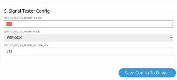
To ensure you do not reach the limit, you may change the following, once in GUI:
- Reduce the tester period interval ((664) in GUI - in seconds [the highest interval possible is 300 sec. = 5 minutes])
- Decrease the size of the testing payload in GUI ((672) in GUI - in bytes [max is 512 B])
❗ Note, that the minimal size of the test message is 64 B.
- Switch the tester mode to MANUAL or MANUAL+PERIODIC to activate the test only when needed (with help of optical probe)
How to Change It in the GUI
Example Explanation
If you were to have a SIM card with data limit of 512 kB and you would send messages of size 512 bytes (which is the maximum size), that would allow you to send 1,000 messages. In order to increase this amount, you could change the size of the test message to 128 B, this would allow you to quadruple the capacity to 4,000 messages.
- Alternatively, you can also remove the battery when not testing to prevent the device from sending periodic messages. This is also beneficial for efficient and long lasting battery use.
Signal Tester Readout (Payload)
The payload is a message sent from the device to the server or vice versa. There are two types of payloads: uplink and downlink.
The uplink payload is sent from the device to the server, and the downlink payload is sent from the server to the device. Uplink is used to send data from the device to the server, and downlink is used to send commands from the server to the device.
The Device Management
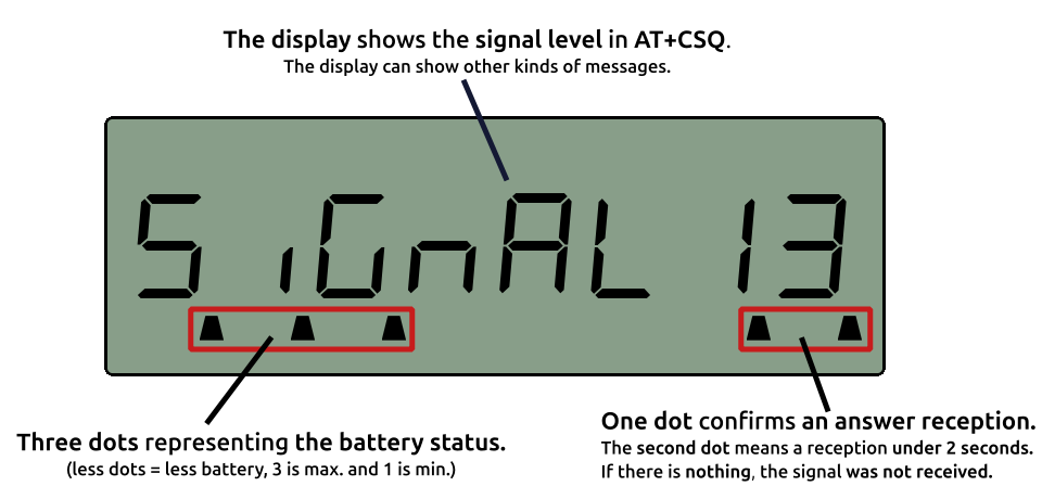
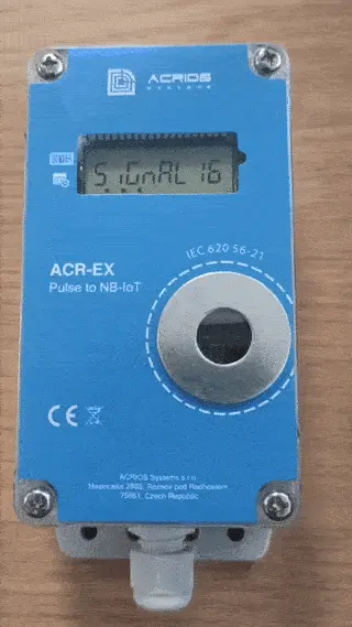
The Device Display
The device uses a Seven-segment display that shows the messages or current value of pulse counter. The display can show various values up to 8 figures and text up to 8 characters.
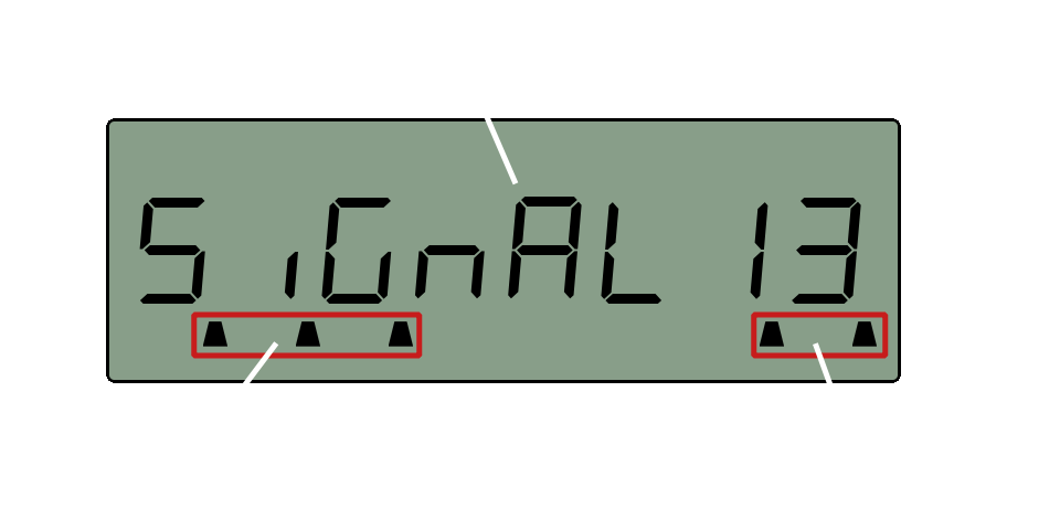
Once you are testing you can see the signal strength values in AT+CSQ as seen in the example picture below.
The value that is showed on the display after signal reception is then sent as a next payload. This way you you can work with the data.
Managing the Devices
By default, the converter is set to Pulse counter mode, therefore there is need to change this configuration to Signal tester mode. The procedure of connecting to the GUI is explained in the section below.
Showcase GIF
There are two main modes of communication with the device:
- IEC - this is a local way using a USB cable via IEC interface
- UDP - this is a remote way of controlling the device (advanced)
For detailed information about IEC implementation and UDP implementation refer to the ACR-EX Display Enabled Pulse to NB-IoT Converter - Integration Manual.
IEC Device Management
GUI Guide
- Connect the optical probe to the computer via USB port.
- Open the browser(Google Chrome or other Chromium-based one is recommended) and navigate to ACR-EX GUI.
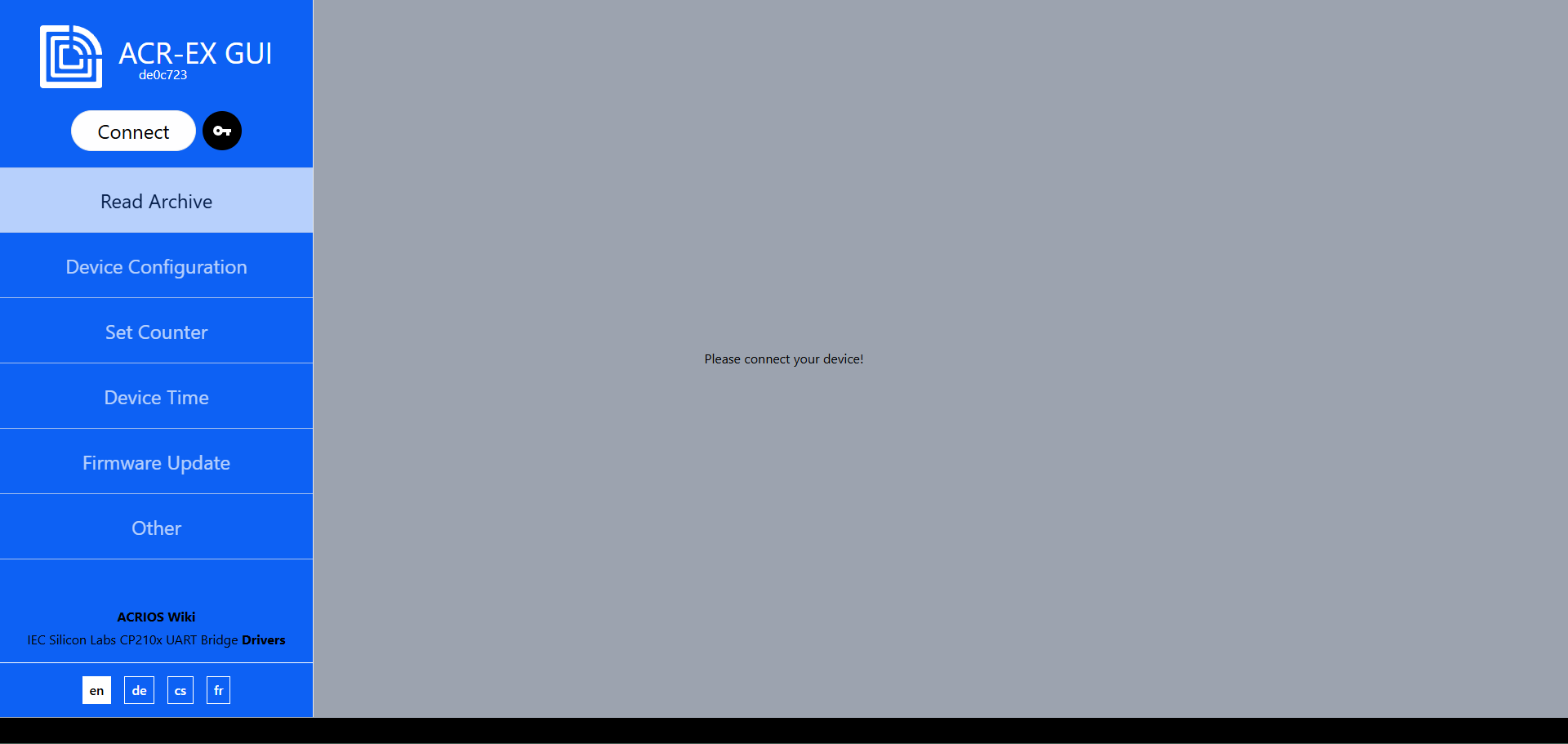
- Click on the Connect button.
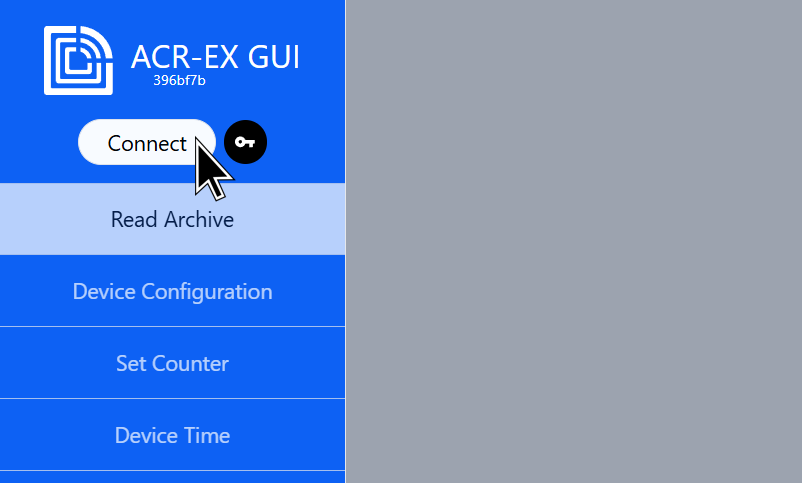
- The optical head should be detected (make sure the driver was installed), select it and click on the Connect.
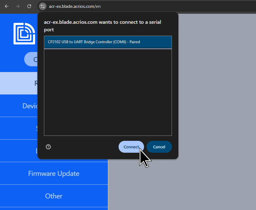
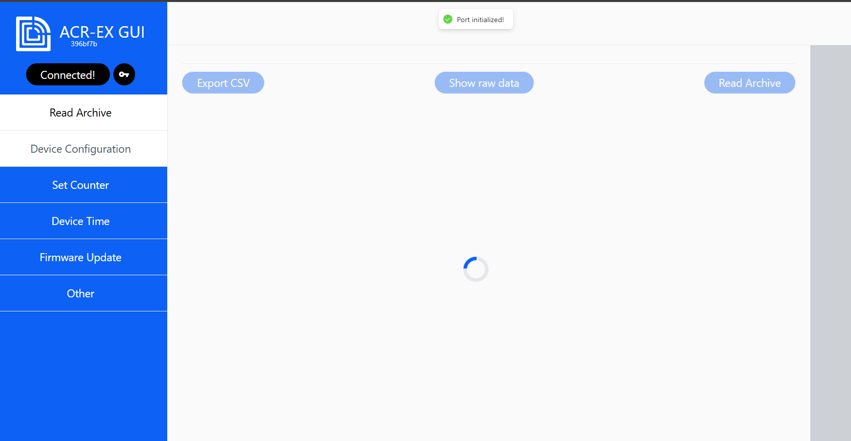
- If you connected successfully, you should see the following screen.
- Enter the IEC mode by triggering the magnetic switch on the right side and putting the head on the top of the magnetic circle (as seen in the gif).
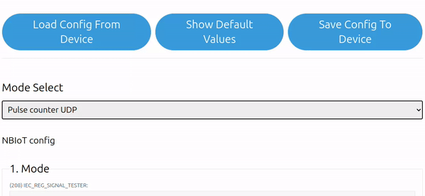
- You can either Load Config From Device or Show Default Values (of configuration).
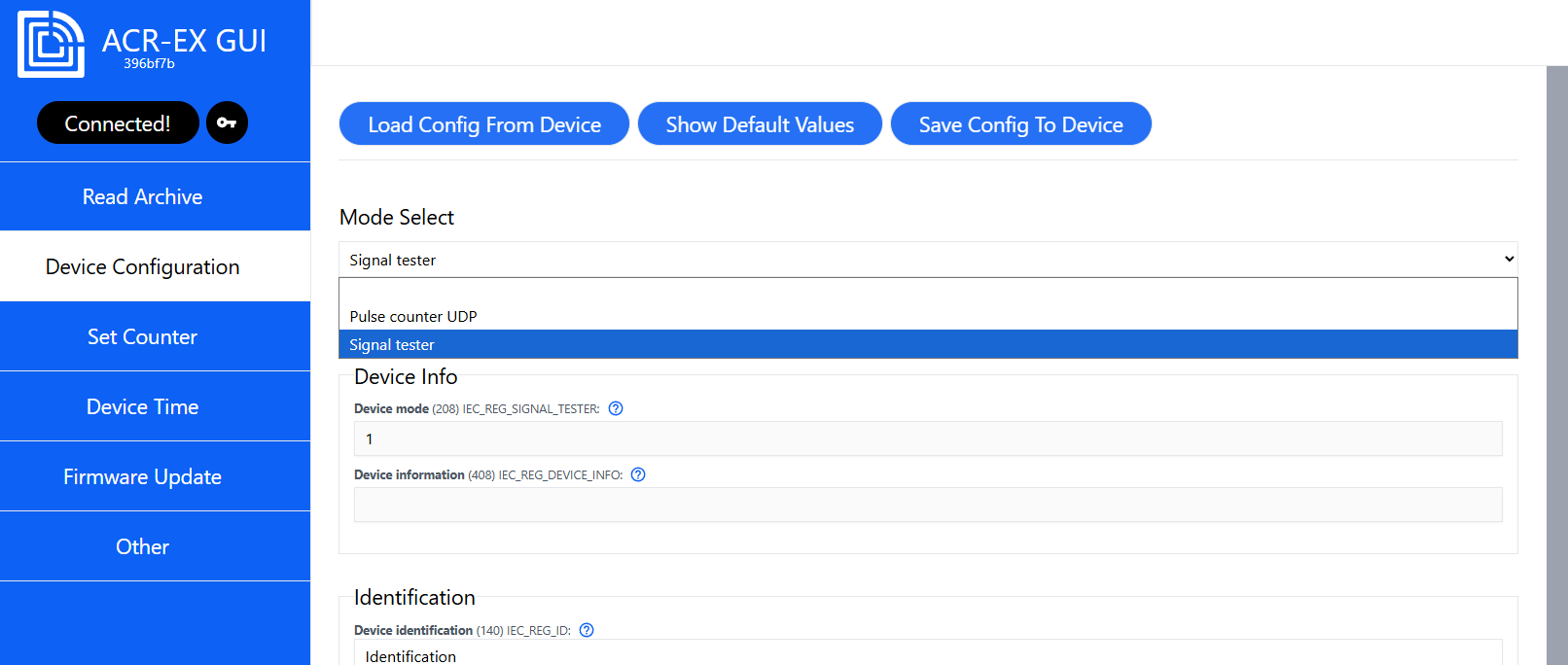
- Configure the device config according to your needs.
- Press Save Config To Device.
Periodic and Manual Signal Testing modes
The device allows for periodic, manual and combined (periodic + manual) testing modes.
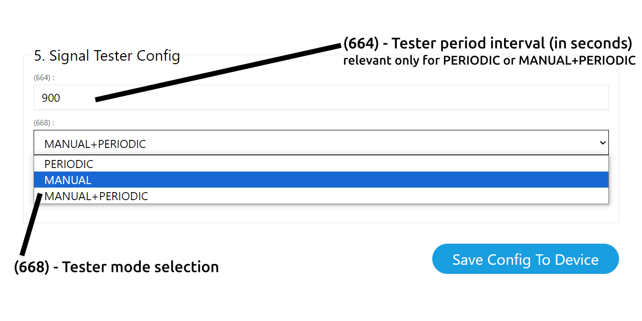
Periodic signal testing
PERIODIC and MANUAL+PERIODIC sends signal test pulses in periods defined by the used in the GUI. This happens as long as the device is active.
❗ Note, that the device will keep sending the messages if the battery stays plugged in. You could either remove the battery, set the signal testing to MANUAL only, or make sure the signal is sent at low frequency. This avoids unnecessary data and energy depletion.
Manual signal testing
MANUAL and MANUAL+PERIODIC sends a signal test pulse whenever you need to. Simply tap the device with the optical head as seen in a following GIF. The device should then show the signal value on the screen.
UDP Device Management
UDP is a lightweight and fast communication protocol designed for time-sensitive transmissions such as real-time communication or IoT sensor networks.
Managing the Devices
Managing our device using UDP protocol consists of sending downlink commands to the device. The device will respond with an uplink payload containing the requested data or acknowledgment.
For more detailed information, refer to the ACR-EX Display Enabled Pulse to NB-IoT Converter - Integration Manual.
Uplink - Payloads Sent by the Signal Tester
Signal Tester with a Coulomb Counter (0xEF)
| Example | Description | Size | Byte Number | Value |
|---|---|---|---|---|
| 0xEF | Command byte | [1B] | 1 | NONE |
| 0x00 0x01 0x00 0x00 | Message sequence number | [4B] (little endian) | 2 - 5 | 256 |
| 0xE8 0x03 0x00 0x00 | Ratio | [4B] (little endian) | 6 - 9 | 1000 |
| 0xE8 0x0D | Battery voltage | [2B] (little endian) | 10 - 11 | 3560 |
| 0x12 | Signal | [1B] | 12 | 18 |
| 0x30 | Temperature | [1B] | 13 | 48 |
| 0x25 0x00 | mAh | [2B] (little endian) | 14 - 15 | 37 |
| 0x60 0x01 | mOhm | [2B] (little endian) | 16 - 17 | 352 |
| 0xD7 0x0D | Input voltage under load | [2B] (little endian) | 18 - 19 | 3543 |
| 0x1A | Degree Celsius | [1B] | 20 | 26 |
| 0xAF 0x25 0x00 0x00 | Pulses | [4B] (little endian) | 21 - 24 | 9647 |
The signal quality can be measured by AT+CSQ to determine the signal quality.
The Table of Signal Values
Table Details
| Value | RSSI dBm | Condition |
|---|---|---|
| 30 | -53 | Excellent |
| 29 | -55 | Excellent |
| 28 | -57 | Excellent |
| 27 | -59 | Excellent |
| 26 | -61 | Excellent |
| 25 | -63 | Excellent |
| 24 | -65 | Excellent |
| 23 | -67 | Excellent |
| 22 | -69 | Excellent |
| 21 | -71 | Excellent |
| 20 | -73 | Excellent |
| 19 | -75 | Good |
| 18 | -77 | Good |
| 17 | -79 | Good |
| 16 | -81 | Good |
| 15 | -83 | Good |
| 14 | -85 | OK |
| 13 | -87 | OK |
| 12 | -89 | OK |
| 11 | -91 | OK |
| 10 | -93 | OK |
| 9 | -95 | Marginal |
| 8 | -97 | Marginal |
| 7 | -99 | Marginal |
| 6 | -101 | Marginal |
| 5 | -103 | Marginal |
| 4 | -105 | Marginal |
| 3 | -107 | Marginal |
| 2 | -109 | Marginal |
| 99 | - | Unknown or Undetectable |
For more detailed information about the payloads sent by the device, refer to the ACR-EX Display Enabled Pulse to NB-IoT Converter - Integration Manual.
Downlink - Payloads Sent by the Server
Please, refer to the ACR-EX Display Enabled Pulse to NB-IoT Converter - Integration Manual for more detailed information about the payloads sent by the server.
Troubleshooting & FAQ
The device is not connecting to the GUI
- Please, make sure to use a Chromium-based browser, such as Google Chrome. Make also sure that the serial line is not opened on any other serial line monitor.
The device is not responding after I have inserted the battery
- This is very likely caused by the bootloader sequence. In order to skip it, put the optical head to the side as seen in the following image. Alternatively, wait for few minutes for it to finish.
The display is showing "no sim" message
- This means that the device has a problem detecting the SIM card. In order to fix it, insert the SIM card correctly and also make sure you use a supported SIM card. The device will check for SIM card once every 24h and with every magnet tap on the side.
The display is showing "no net" message
- This means that the device has a problem detecting the network. The device will check for network once every 24h and with every magnet tap on the side.
I have not found information I was looking for in this article
- Please, refer to the ACR-EX Display Enabled Pulse to NB-IoT Converter - Integration Manual.